Scratch Vega 1 Original Design / Scratch Built
Scratch - Vega 1 {Scratch}
Contributed by Leonard Loranger
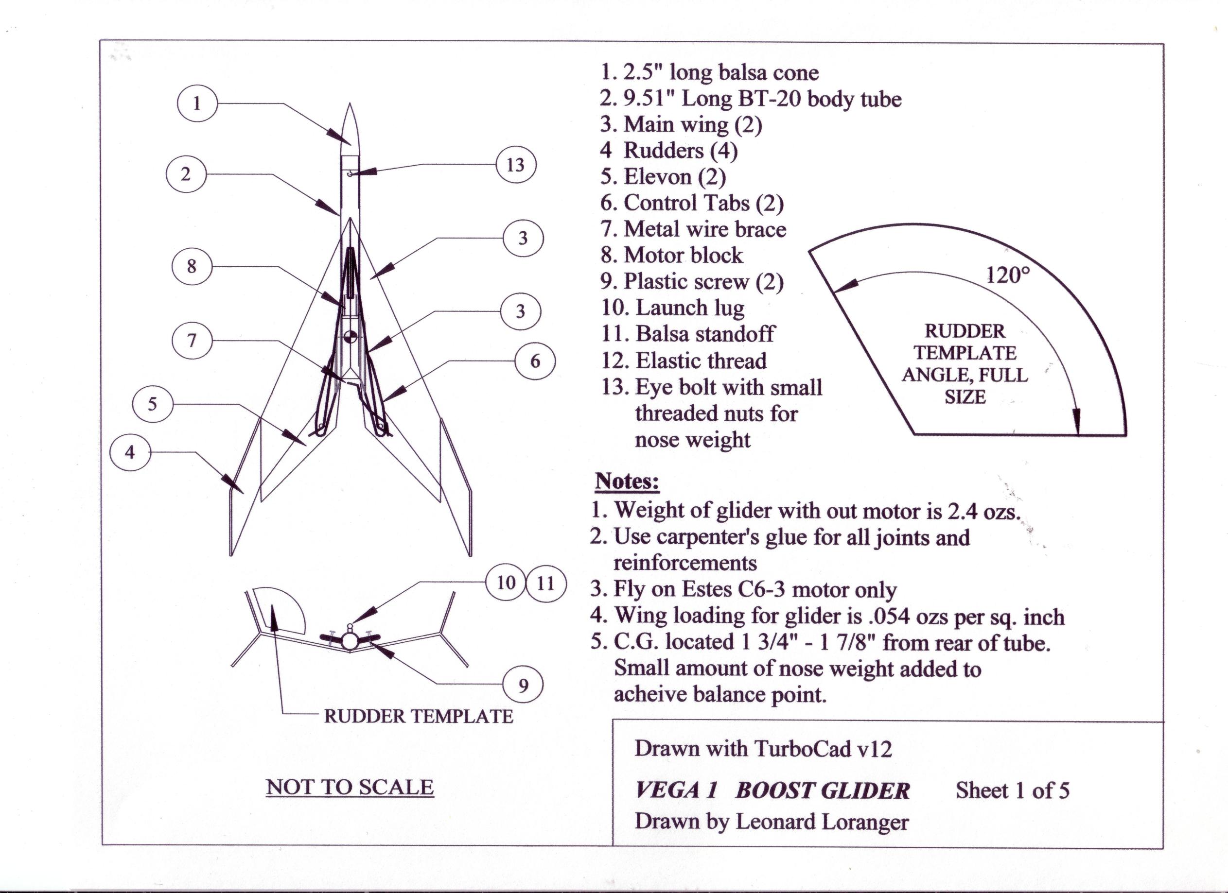
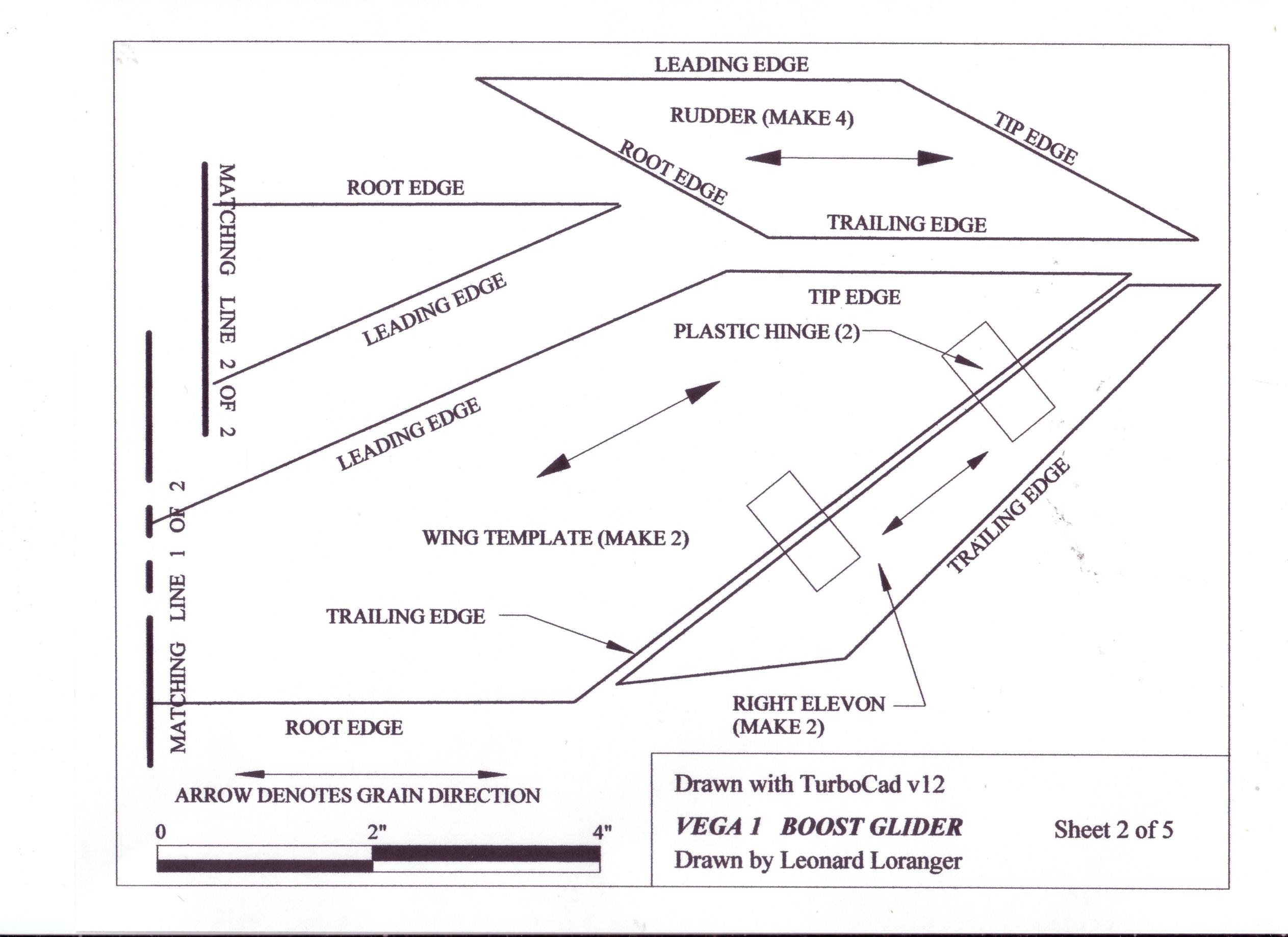
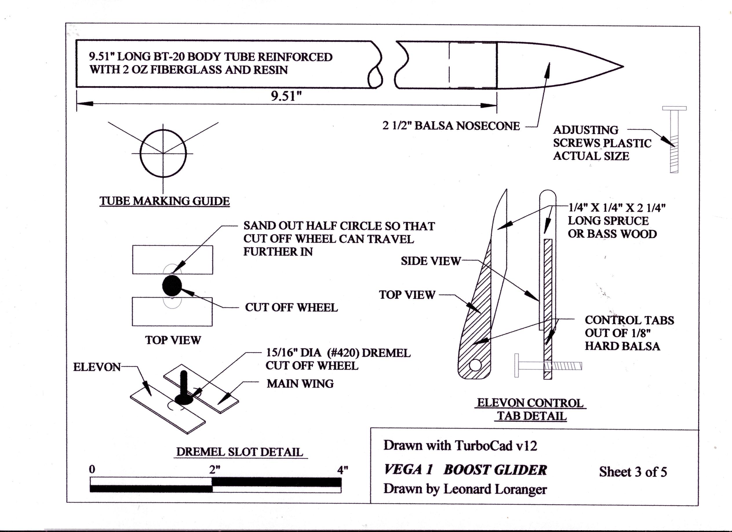
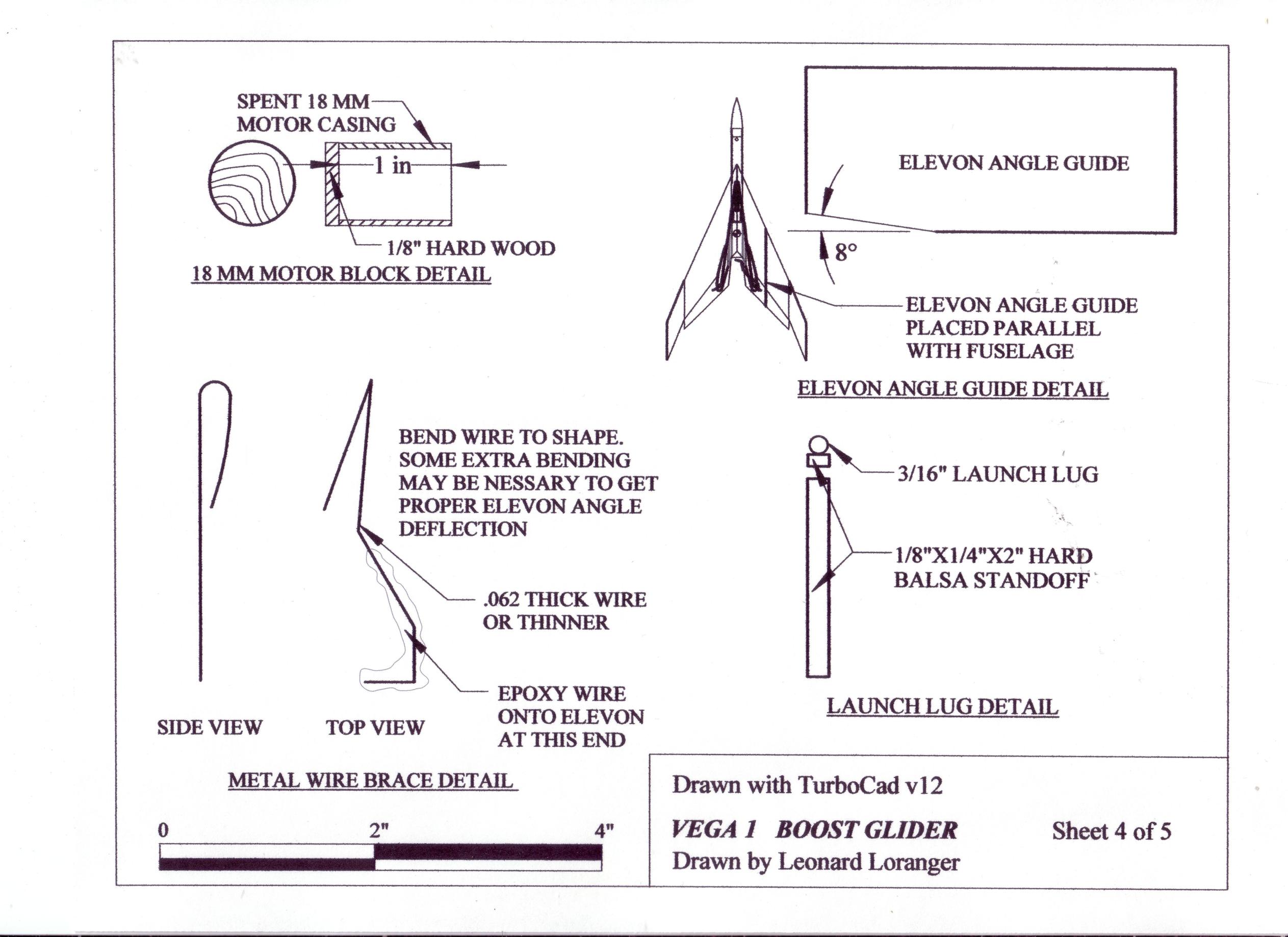
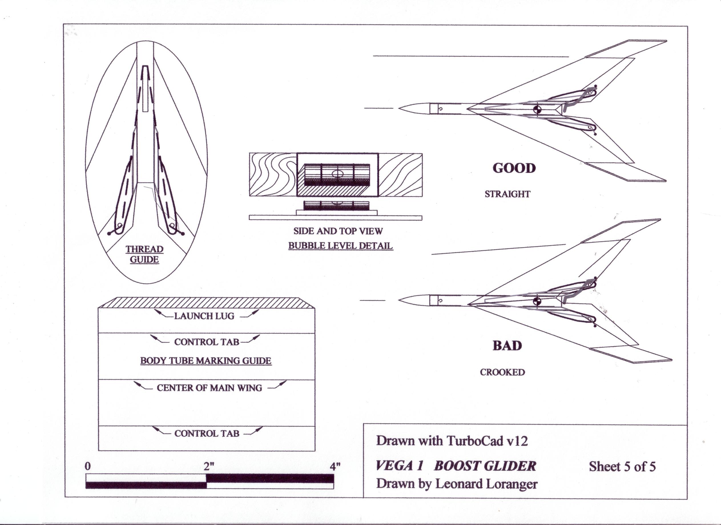
The Vega 1 is a high performance rear engine boost glider designed for dramatic flights on Estes B6-2, C6-3, and C6-5. With its sweptback wings and long length, Vega 1 will fly straight as an arrow. Introducing a slight spin will also ensure the model will be stable. The balsa that will be used for this project will be out of rigid 1/8" thick C-grain balsa and is heavier compared to A and B-grain balsa. A quick search on the internet may help you to find more information about the different varieties of balsa. Construction: Instruction Sheets: In addition to the materials listed on Sheet 1 of 5, you will need the following items: Read the directions a couple of times and become familiar with the different drawings and parts before you assemble the Vega 1. Page 1 of 4 is an assembly drawing. After you have cut all balsa parts be sure you have the following, Start the control tabs by looking at the detail drawing on Sheet 3 of 5. Pre drill and thread the holes before cutting them out. Cut the control tabs from 1/8" thick hard balsa, and the bases out of 1/4" X 1/4" X 2 1/4" long spruce or bass wood. To avoid splitting, Test fit the glide control bolts to make sure they are not too tight. If they are to loose, you may have to fill in the holes with glue and trial fit again. Carefully cut and glue each assembly making sure you have a left and right. A scroll saw will cut these parts easily. When finished both assemblies, you should have a right and left part. Fuselage Sometimes a boost glider not trimmed correctly can result in a fast spiral glide down. Using an Estes BT-20 body tube by itself will not be strong enough during some of these landings. The thin walled tube has a tendency to wrinkle. Reinforcing the tube with 2 oz glass cloth and resin is an easy way of fixing this problem. Another alternative is to buy heavier walled tubing if you can find some. A nosecone will have to match the tube or you can turn one out on a lathe or drill press. Visit a local hardware store and pick up some ½"diameter copper tubing. The tubing should be ½" diameter on the inside and 5/8" diameter on the outside. The copper tubing need only be about 24-30" long. Use the copper tubing as a mandrel for handling the Estes BT-20 tubing while laying on the fiberglass and resin. Apply two layers of car wax on the copper tubing and buff off after. This will keep any extra resin and fiberglass from sticking to the copper mandrel. Polyester resin used for auto and boat repairs works fine. A local hobby store will carry 2 oz glass cloth or you may need to look on the internet. Before mixing the resin, follow the mixing instructions and make sure you wear safety glasses and latex gloves to protect eyes and skin. Always work outside if you can where there is plenty of ventilation. Start by passing an 18" Estes BT-20 tube over the copper mandrel and taping both ends in place with masking tape. Cut out a piece of 2.5"x 12" wide glass cloth to size making sure that you will have enough to cover the entire BT-20 tube with some overlap lengthwise. Mixing resin and hardener with paper cups (the ones used for hot drinks) works well. Mix the resin and hardener together per directions and apply a thin coat with a small brush on to the BT-20 body tube. Hold one end of the copper tube while the other end is on the ground. Place the fiberglass lengthwise on the tube. Dab a little resin on the brush and brush out any dry spots on the cloth. Be careful to work out any bubbles that develop. The white cloth color should change to a transparent color when wet with resin. Holding the copper tube at one end, continue laying the rest of the cloth on all the away around until it overlaps the beginning. Use the brush to wet out the rest of the cloth. If the cloth at any time seems to become tacky or starts pulling away from the tube, stop. The resin may be starting to set up. If this happens, stop any more work for another 24 hours until the resin cures. The working time with polyester or epoxy resins may only be 5 or 10 minutes or so depending on temperature and humidity. Working with fiberglass and resin becomes easier with time and practice. Sand any extra resin away from the tube with 220-grit sandpaper. Use a sanding block to accomplish. Start by sanding the tube lengthwise carefully hitting all the high spots and not to sand thru the fiberglass. Another way to get a smooth finish is to sand in 45-degree directions along the axis of the tube. Roll the tube at the same time while sanding with the block. This method of sanding follows the path of the spiral wind in the tube. This will give you an even finish all the way around. Mixing up and brushing on a second thin coat of resin will fill in any low spots left behind. Remember, sanding most of the resin will help to save weight. Repeat this process until you are happy with the finish. Dent and fill auto primer can help with filling any small imperfections in the tube finish. After the tube is done, cut the tube to a length of 9 ½". Cut out the body tube-marking guide in drawing 5 of 5. Wrap this marking guide tightly around the body tube. Mark out the centerline positions of the launch lug, control tab, wing, etc, with an L shaped piece of metal or smooth door jam to finish drawing lines lengthwise on the tube. Look at the 18mm motor block detail shown on drawing 4 of 5. Cut a spent 18 mm motor to a length of 1" and glue a 1/8" x ¾" dia plywood plate at one end. Reinforce the plywood plate on the inside with more yellow glue. Place a little dab of glue at the end of a cotton swab. Reach through the rearward end of the BT-20 body tube 3" forward and make a circular pattern with the cotton swab. Be very careful not to get any of the glue near the rearward end of the body tube. Insert the motor block with the plywood plate facing the rear in the end of the body tube. Then, using spent engine casing, push it forward until the end of the engine casing is just the even with the rearward end of the body tube. Caution: once you have inserted the nose block far enough to come in contact with the glue to not allow it to stop until it is in the proper position. Some glues dry very quickly, and stopping for as long as a second may cause it to freeze in the wrong place. Remove the spent engine casing as soon as the nose block is in place. Nose cone construction Purchasing BT-20 size nose cones or using a lathe to turn down a nose cone is another avenue. Wing construction Cut out all the templates from Sheet 2 of 5. Match the lines for the right wing and tape them together. 1/8" x 3" wide, c-grain balsa should be large enough to fit the whole wing template in place. Follow the direction of the grain as shown. Trace the rest of the templates on to 1/8" rigid C-grain balsa. After cutting a left and right wing, sand a rounded edge on the front and back of both wings to give a smooth airfoil. Know is the time to mark location centers for all four hinges for the wing and the elevon. Let us look at the hinge Dremel slot detail on Sheet 3 of 5. Using the Dremel #420 cut off wheel, set the wheel in the drill press chuck and raise the drill press table with the wing on it so that the cut off wheel is half way up the thickness of the wing. This will take some adjusting of the table. Then using a small round sanding tool make a small 1/8" hole where the center mark locations are. Then proceed to cut out a slot as far as the cut off wheel will allow. The 1/8" hole should leave enough room for the plastic hinge to slide in to the cut out slot. If it still does not seat all the way in, then cut a little bit of the square edges off on each corner. Repeat this process 8 times. Rough up the hinges with 60 grit sand paper and glue all four hinges into place on the wing. When the glue is dry, attach and glue the elevons in place. Sand the elevons to shape as shown in the drawings. Wing and fuselage assembly The amount of dihedral angle is very critical, (by the dihedral angle, we refer to the angle made by the wings, and the body tube where the wings point upward rather than straight out. Drawing on page 1 of 5 clearly shows this angle on the rear view. The outer edges of the wings are even with the top surface of the BT-20 body tube. The following method will make the right amount of dihedral angle. Place the root ends of the wings tightly together and secure with two strips of tape. Put a line of yellow glue down the wing centerline on the body tube and then lay the wings on top. Align the root edges of both wings on the body tube. The trailing edge of the wings is to be even with the rear of the BT-20 body tube. Press the glue joint firmly to be sure the wings are set evenly and tightly against the BT-20 body tube. While the model is drying, the wingtips and the complete length of the BT-20 body tube should be lying flat against the table. Use small weights to accomplish this. Do not handle the model until this glue joint is completely dry overnight. Reinforce the BT-20 body and wing with another glue joint on both sides. This should help the wing from popping off after some hard landings. Rudders Sheet 2 of 5 show the rudder patterns. Cut the rudders out of 1/8" C grain balsa. Make sure you follow the grain direction. Glue 2 of the rudders by there root edge. Use masking tape to keep together. Both rudders should be sweeping backward when glued together. Use the rudder template guide to get the 120-degree angle needed for spacing. Repeat the process for the other rudder assembly. Set these rudder assemblies to dry overnight. Before gluing the rudders on the wing tips, make sure the wing tip surfaces are parallel with the main body tube. Use a small bubble level bought at any hardware store to check for this. Sheet 5 of 5 shows a full size drawing of one. This one was purchased at Home Depot and mounted on a small piece of scrap wood for more accuracy. Place the model so that it will not move around when taking these level measurements. Place the bubble on the BT-20 body tube and level it. Now check the wing tip and make sure that it is level. If it is not level then some sanding will be required until it is. Make sure not to take too much off or one wing will be shorter than the other. Repeat this process for the other side. Glue the rudder assemblies on the wing tips using the rudder template guide. Almost finished Install the control tabs following the markings on the side of the fuselage. Looking at Sheet 1 of 5 will give you a good idea where to place them. Glue the launch lug and spacer together as an assembly then place along line as shown on Sheet 1 of 5. Cut a length of .04 thick wire to shape as shown on Sheet 4 of 5. Adjust the wire until there is 8 degrees of downward deflection. Run the elastic thread through the holes drilled in the trailing edge of the elevons. Tie the end of thread with a knot large enough not to pass thru the hole. Make the thread long enough so that it can pass around the plastic bolts and in front of the launch lug spacer yet have enough tension to get the elevons to snap up once the motor pops out. Balance the model on a ruler to find the center of gravity. The model should balance 1 3/4"-1 7/8" from rear of tube. If it does not then add more weight to the nose by drilling a small hole and adding a steel eye screw with bolt nuts for weight. Let’s go outside and test this thing Make sure your model balances evenly left to right. You can check this by balancing a ruler down the center of the body tube lengthwise. If the model is a little heavier on one side than the other, compensate by adding a little weight to the opposite side. Apply a little more glue for reinforcement or clay to the side that is lighter. Trimming the glider will be much easier if the model balances evenly from left to right. The gliding characteristics of the Vega 1 can change by turning the glide adjusting screws. It is best to determine first the proper setting to get a straight flight. Prevent damage to the model by finding a tall grassy area to hand launch. To test the glide, grasp the model by the fuselage body and Turning the adjusting screw counter clockwise will accomplish this. Turning the adjusting screws in ¼ or ½ turn increments can make small accurate changes in flight. If you want the model to turn left repeat the same procedure for the left elevon. Turning the adjusting screw 1/2 to one complete turn creates a close circle and fast recovery. On windy days (10-15 mph winds), it is best to set the glide for a fast recovery as described above. This is the keep your glider from landing to far way from the launch pad area. Up up and away!!!!!! Vega 1 requires one Estes C6-3 or C6-5 motor. This model can launch from a standard 3/16" x 36" launch rod. When inserting the motor make sure that the right elevon deflects down. The left elevon may deflect up a little bit; this should not be a problem. You can use the 8-degree pattern guide on Sheet 4 of 5 to double check the right elevon alignment. Place the right elevon angle guide as shown in Sheet 4of 5. Your only looking for the front surface of the elevon part to line up, not the tapered end. Hook up the igniters and launch. Watch the boost glider to see how it performs. If the model turns steeply left to right, remember to go over the adjustment features to correct the flight. After a while, you will get a feel for what the model is doing. Please email me if you have any questions or comments you would like to make. My email address is draftsman8384@yahoo.com Summary: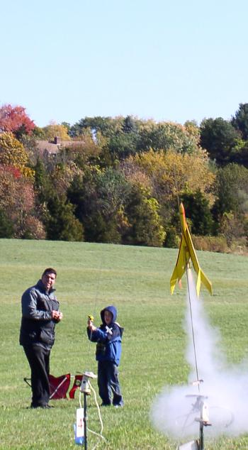 Brief:
Rear engine boost glider with high altitude performance. Rugged and built to perform even on windy days.
 part of the front wing and throw it through the air into the wind. If the model nose-dives, adjust the elevons so that they pitch up. Turn both glide control-adjusting screws so that the elevons move up. If the model stalls, reverse the process. Repeat this testing and adjusting until the model glides straight ahead when thrown. The model should glide for about 15-20 feet. To set the glider for a slight right turn, adjust the right elevon so that it sits a little higher than the left one.
Build it and you will not be disappointed.
Sponsored Ads


 |
 |