CLICK PICTURE TO GET FULL SIZE
 |
 |
 |
 |
|
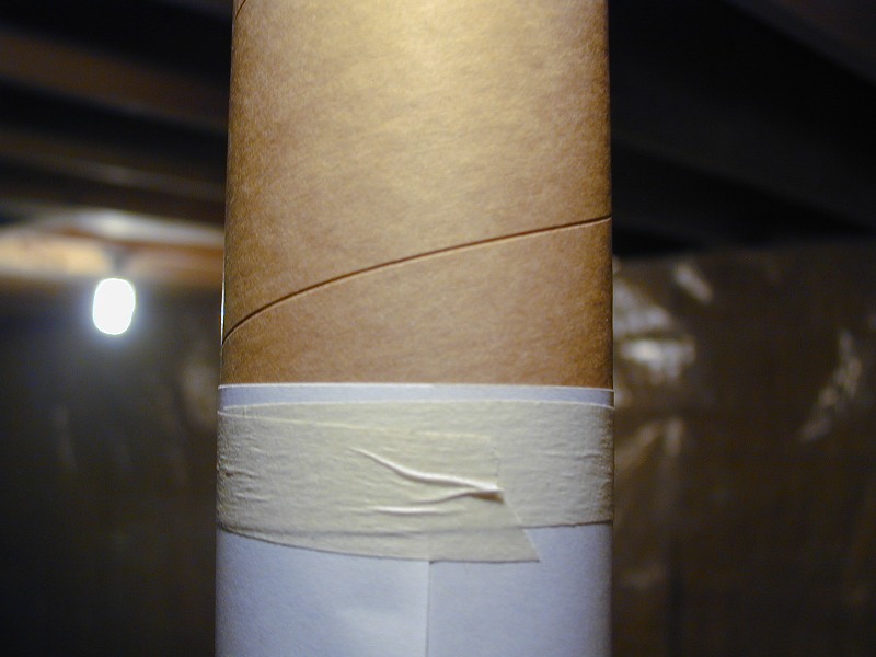
| Technique 1: This shows the use of heavy printing paper to mark the tube equally around the circumference. This can be used to mark for cutting with an Exacto Saw (you may want to leave the paper in place while cutting). It can also be used for marking the tube for fins or altimeter holes. |
Technique 2a: This picture illustrates an option for motor retention. Take (2) two 4" lengths of 3/8" wooden dowel. Pre-drill a 13/64" hole centered in the top of each dowel to about 1/2" depth. Using a minimal amount of epoxy, coat the treads of an #8-32 Brass Threaded Insert and screw it into the hole.WARNING: Keep the inside treads free of epoxy. | Technique 2b: Thoroughly coat one dowel on the two sides that will press up against the fin and motor tube. Slide it into place and let dry. Repeat on the other side. |
Technique 2c: Here are two options for motor retention clips. On the left is a Screen Door Clip and on the right is a T-Nut Fastner (make sure the screw hole is larger than the screw) NOTE: since my version only uses electronics, friction fit is actually good enough....but just in case. |
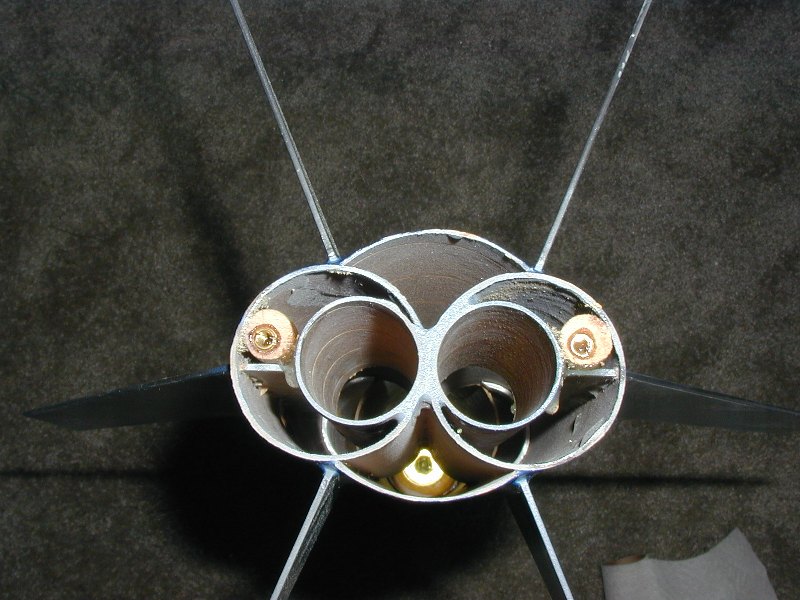
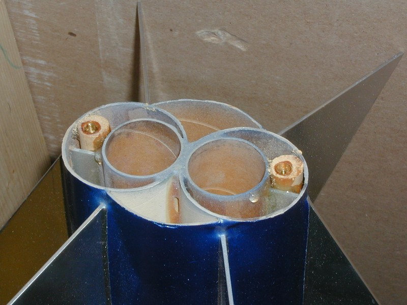
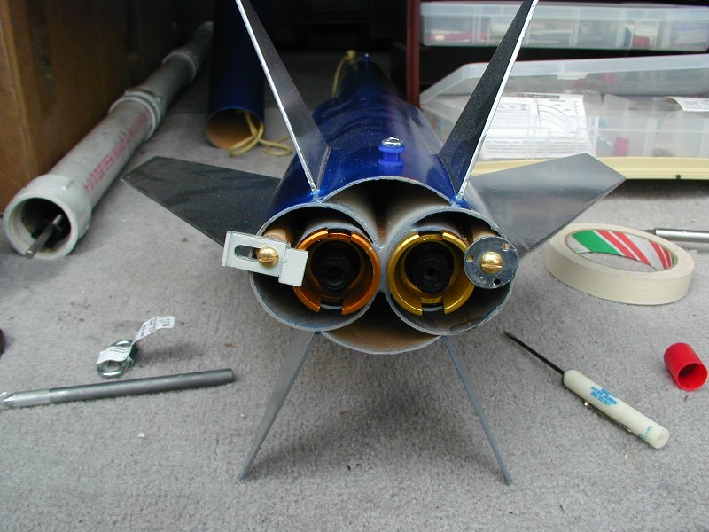
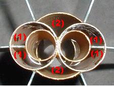
Technique 3: Launch Lugs. You will want two lugs or buttons for this rocket. Placement should be at 1/2" from bottom of rocket and 1" from top of bottom body tube (the one with the fins and motor mount) CG (w/o altimeter) = |
 |
 |
 |
 |
 |
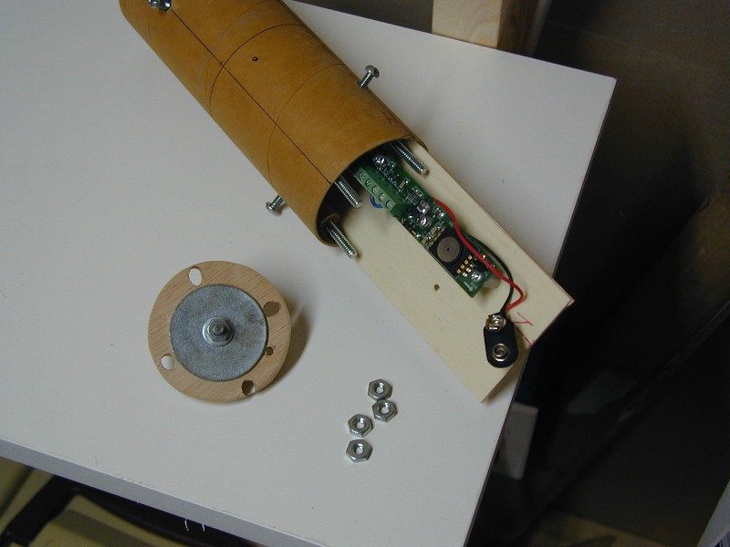
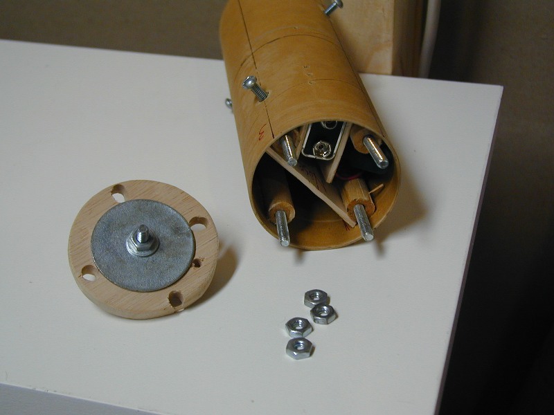
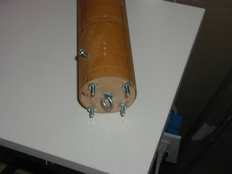
| Technique 4a: There are different methods for building altimeter bays (here's one). The technique I used is very similar with the following changes: 1 - I used (4) interior posts (dowels) to allow more (4) verses (2) points for attachment of the "cap" 2 - I installed a large flat washer on the back of the "cap" to help distribute the stress upon ejection |
Technique 4b: The mount board is cut to fit under two posts (dowels) so that there is no slop. It is wedged between the posts and the angle of the tube. Make its length so that it does not move back and forth vertically. Ensure your battery is mounted so that it will not move even upon a hard impact. NOTE: I used a 1 3/8" Closet Pole Scoket Set that I filed and sanded down for the cap (I wanted the thickness) |
Technique 4c: In the configuration I made, the electronics bay was removable from both sections of tube. I used two screws in the top tube and two screws (off-set by 90 degrees) in the bottom tube. NOTE: I used duel-threaded hanger bolts instead of threaded inserts. |
Technique 5: The Bottom sections (1 & 2) will need to be closed off to prevent your ejection charge/gases from escaping out the back without deploying your parachute. This may be a good place for 2-part foam, the closer to the top of the motor tube the better (reducing the volume) Ensure that you use ample epoxy and fillets on the "flaps" of the main body tube. The ejection charge may want be too much and cause this to blow out |
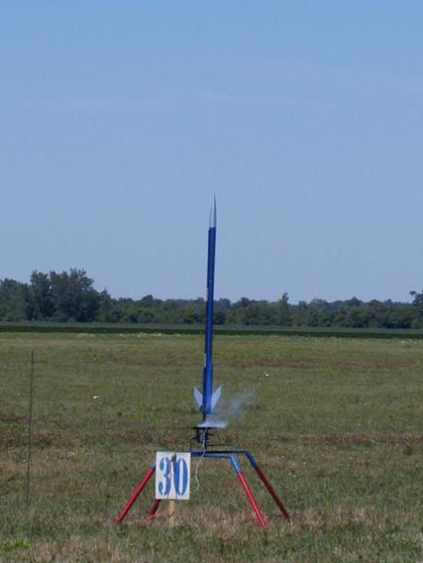
Picture 4: This was its first launch at NARAM-43 on (2) G35's to 1011 feet according to a G-Wiz Altimeter. (Ejection charge removed from the motors). I had a second successful flight at NARAM-43 on (2) G80's but the second ejection charge tripped the G-Wiz and I didn't get altitude. A third launch at 3-Oaks in November on (2) G80's yielded an altitude of 1562 according to the Missile Works RRC2. |